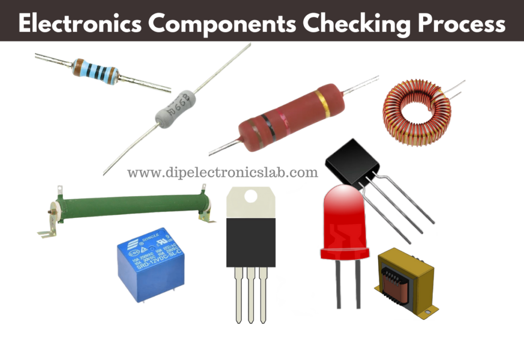
Hi, guys in this post I will give you a total explanation of the Basic Electronics Components checking technique. If you want to learn about the basic electronics components checking technique read this post till the end.
here you will get lots of electronic information and electronic gadget repairing techniques. As well as you will get an electronics device software download link for free of cost. All company LCE LED TV repairing techniques and software download links also get here.
So If you want to get some other information about electronics you can comment down below your message or describe your question.
Basic Electronics Components Checking Technique
Table of Contents
To check the Basic electronics components you have to know about the unit of electronics components. Let’s discuss about basic electronics components checking and testing process.
- Resister Checking Process:
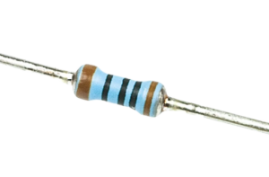 All are you know about resistors. This is the first basic electronics components. This component uses to implement resistance in the electronics circuit. The Unit of this electronics component is Ohm (Ω).
To check this component using a multimeter you have to set your multimeter on Ohm range. After that touch your multimeter probe on two sides of the resistor component. If you get the proper value this means your resistor is OK. And you can use it in the electronics circuit.
2. Diode Checking Process: 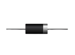 To check a Diode you need a Digital Multimeter because at this time digital multimeter is the best instrument to check electronic components accurately. So first of all set the multimeter at the continuity point and touch the multimeter probe with the diode legs. If you get some values on the multimeter display like 340 to 680 then your diode is in good condition, but if you get beep sound from the multimeter from two side of the diode then your diode is in bad condition. This is the easiest way to test and check a Diode is good or bad.
3. Transistor Checking Processing:  To test the Transistor good or bad, you just need a Digital Multimeter to test the transistor. You just need to touch a multimeter probe on the transistor middle terminal (led) and the another pin of multimeter you need to touch any of the two terminal of the Transistor. After touch the multimeter probe on the transistor legs, if you get any beep sound or blank value then the transistor will be in bad condition. And if you get some values like 340 to 700 on the digitam multimeter the the transistor will be in good condition. To know more about the basic electronics components you can buy our basic electronics components book “Understanding Basic Electronics Components” by Dipankar Das.
4. 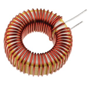 Inductor Checking Process: It is very easy to check and the an Inductor using Digital Multimeter. To test an Inductor you need to set the multimeter in continuity mode. After set the multimeter in continuity mode you just need to touch two multimeter probes with the two Inductor coil. If you get beep sound with some values in the digital multimeter, this means the Inductor coil is in good condition.
These are the most common and basic electronics components which we will see in a electronic circuit. If you want to know others’ basic electronics components checking process, just comment down below, I will make a detailed article based on your comment. And if you get more electronics-related news and articles, you can subscribe to our site.
4. Capacitor Checking Process: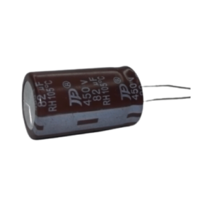 This is the only component that needs a separate feature multimeter. This means if you want to check and test a capacitor you need a capacitance testing multimeter. Normally low budget multimeter does not have capacitance testing features. So to test a capacitor you need to buy a Capacitance testing multimeter and then you have to touch the multimeter probe with the capacitor legs. The RED probe connects with the positive terminal of the capacitor and the BLACK problem connects with the Negative terminal of the capacitor. After connect those probe with the Capacitor, you will see the value of the capacitor on the Multimeter display.
If you test a 10uF capacitor the you will see 10uF value on the multimeter display. This is the process of Checking a capacitor..
Read our Others Basic Electronics Articles
- CD LED TV repairing Guide Ebook in Hindi
- How to Convert Monitor Into LED TV
- S368A1.5 Universal Android Motherboard All Features with Buying link
- SP36811.2 Android motherboard all features and buying link
- LCD LED TV Repairing common Problem and Solution
- LCD LED TV Panel datasheet downloading technique
- What is LVDS Cable and How to match it
- What is LVDS Signal Total information with Value
- How to repair No Display Sound OK problem of LCD LED TV
- Visit Our YouTube Channel for Video tutorials
Watch video tutorial of Basic ELectronics Components Checking
FAQ of Basic Electronics Components Checking Process
What do we need to consider in testing electronic components?
I personally check only two things in a basic electronics components to understand, components is good or bad. One is Continuty and another one is resistance. These are the two things, which help us to identify a good and a bad component.
What is the importance of checking testing electronic components before using?
In my opinion the importance of checking and testing component before using is requirements and needed the components meed my specification or not. Everyone need to check and test the quality of sourcing electronics components.
Testing electronic components with multimeter pdf
If you want to know the actual practical process of checking basic electronics components just buy our “Understanding Basic Electronics Components” and know everything about basic electronics components on a electronics technician prospective.
