5-24V STR Power Module Installation

Almost every electronics technician uses a power module for repairing work. Mostly it is used for power supply repairing. This power module help to modify power supply. 5-24v STR module has 4 wire which I discuss in the below of this post in detail.
5-24v power module is a chines STR kit which we use for power supply bypassing. This module is very easy to install in the normal power supply. I install this module many times while LCD LED TV power supply repairing.
I know you are all want to know how to install this module in the power supply. Don’t worry I will explain to you complete details. This module make with international management system quality. But you have enough knowledge about electronics which need during installation.
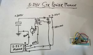
In the above picture is about the connection of 5-24v Power module. Here in the picture I explain the extract connection of 4 wires. Every wire has a different color. That is RED, BLACK, Yellow, Green/Blue. All these wirework for bypassing the power supply primary section. RED and Black wire you have to connect in the primary section. And Yellow and Blue wire you have to connect in the secondary section. Let’s discuss where you can connect which wire.
Where connect which wire ?

BLACK WIRE: Black wire you have to connect on the Primary section main capacitor’s negative point. Where we get 300v to 400v in the primary section. Before connecting the black wire make sure the capacitor is not short. If the main capacitor getting short, at first change that capacitor.
RED WIRE: Red wire you have to connect on the Main transistor base point. You all know when we install this module. When STR or power transistor getting damage. So first of all remove that power transistor and connect the RED wire on the base point. If your transistor has more then 3 legs then connect the red wire which goes to SM transformer. In every single power supply make with this technique. To find out the SM transformer point which was connected with power transistor.
Yellow Wire: very easy to connect the yellow wire. Just find out the secondary section main capacitor like 12v and 24v and connect on the positive point. If your power supply has more the 24v output supply then you can not able to install this module. Before connecting the wire check the capacitor for safety. If you get a bad or abnormal capacitor, replace it with a new one. That’s it.
Blue Wire: This blue wire you have to connect on the secondary section ground point. It is very simple to connect.
All the 4 wires connect successfully in the power supply. Now you have to do some more work to complete the installation process successfully. If you want to watch video footage of the installation of this module click here.
Now ON the power supply and check the output voltage. If output voltage getting high or low adjust the voltage doing preset variation. You will get the preset in the power module which you install in the power supply.
Your Job is DONE. For more content click here.
Related Post Which I post on this site
- LCD LED Panel Repairing Process
- How to Repair TV Stand by mode
- LCD LED Panel Burning Problem Repairing
- Power Supply Repairing Technique
- LCD LED Repairing Guide PDF
- T-con Board Repairing Process
- How to Repair LED TV NO Sound Problem
Thank You


